A manufacturer specializing in the production and research and development of testing machines, integrating pre-sales consultation, research and development, production, manufacturing, and service
Current location:
Home >
News>
Company News>Electromechanical Universal Testing Machine: A Practical Selection Guide
An electromechanical universal testing machine uses a controlled mechanical drive to move a crosshead and load the specimen. It can be a useful platform for a range of tensile, compression, and fixture-based tests when its capacity, travel, sensors, and accessories match the application. Selection should connect the drive description to the actual specimen programme. This guide explains the decisions that matter when comparing an electromechanical system for a new or expanding laboratory.
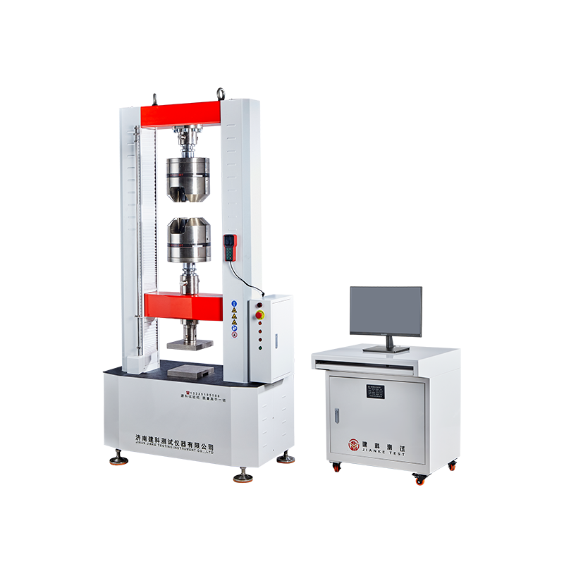
WDW-300 — Computer controlled electronic universal testing machine Hydraulic clamping. Product illustration. Confirm the exact configuration for your specimens.
Translate the specimen programme into a frame configuration
Begin with the materials and properties the laboratory will test during normal work. A rigid metal coupon, an extensible polymer strip, and a compression fixture can occupy very different working spaces. The frame must accommodate the installed grips and adapters as well as the original specimen length and required movement. A catalogue height is not the same as usable test space.
Next consider how often the arrangement changes. A laboratory dedicated to one specimen family can choose a stable fixture setup. A mixed laboratory should evaluate the time and verification needed to change grips, force sensors, or deformation devices. Quick mechanical changeover is useful only when the correct measurement configuration can also be restored reliably.
Discuss the relationship between load and speed using the proposed test stages. Ask for a representative demonstration at the required load and movement, rather than a statement about unloaded maximum speed. Explain whether the method requires direct strain control or another feedback mode. Finally, connect the proposed hardware to training and service access. A drive that looks attractive on paper should still be straightforward for the receiving team to commission and maintain.
An illustrative application review
Imagine an illustrative laboratory adding plastic dumbbells to an existing metal-test programme. The required plastic extension is larger, while the expected force is smaller. Selecting a larger-capacity version of the existing frame would not necessarily solve either issue. The buyer instead compares usable travel, a suitable low-force sensor, polymer grips, and a deformation device. The decision is documented against the two specimen families, allowing the laboratory to see where a shared configuration is practical and where separate setups are justified.
Assess the screw drive and working space together
An electromechanical testing machine usually converts controlled motor rotation into crosshead movement through a mechanical transmission. Its usefulness depends on the complete drive, guides, force measurement, working space, and control arrangement. Ball-screw terminology alone does not establish achievable accuracy, usable stroke, or the quality of a test near a particular material's yield region.
Check usable specimen length after the grips and extensometer are installed. Confirm speed capability under the required load, the relevant travel limits, and the procedure for returning the crosshead between specimens. A tall frame may be needed for elongating specimens, while a shorter working space can be adequate for other jobs. Compare the quoted configuration using representative fixtures and actual test movement. This avoids confusing the machine's unloaded travel specification with the available motion during the laboratory's intended test.
Size the force measurement system for the actual specimens
Start with the largest credible breaking load and the smallest load that must be measured reliably. For a tensile specimen, an initial engineering estimate is expected tensile stress multiplied by original cross-sectional area. If stress is expressed in MPa and area in square millimetres, the result is newtons. This estimate helps select a configuration, but it does not replace representative sample testing. Allow for material variability and the approved operating limits of the frame, grips, fixtures, and sensor.
A high frame capacity does not establish measurement quality at every lower force. Ask for the verified working interval of each force transducer in the direction being used. A laboratory testing both strong steel and light plastic specimens may need different load cells or separate equipment. Compare uncertainty, usable measuring range, overload protection, and installation effort instead of choosing solely from the largest number on the quotation.
Treat grips as part of the measuring system
A tensile test works only when the force enters the specimen through a suitable, repeatable load path. Flat strips, round bars, wire, films, and finished components require different contact geometries. Jaw faces should hold the sample without producing a premature failure that makes the measured result unrepresentative. Neither a stronger clamp nor a rougher surface automatically improves the test.
Provide the supplier with specimen drawings, thickness or diameter ranges, shoulder geometry, expected force, and any restrictions on marking. Check insertion depth, alignment, clearance, and the maximum load permitted for each grip assembly. During a demonstration, examine the fracture location and the shape of the force curve for evidence of movement in the jaws. Keep gripping instructions within the operating method so that a change of operator does not silently change the way force is transferred.
Separate specimen strain from crosshead travel
Crosshead travel includes more than the extension of the measured specimen length. Grip seating, frame deformation, fixture compliance, and occasional slippage also contribute to the movement recorded by the machine. Consequently, a smooth travel curve cannot by itself establish an accurate elastic modulus or proof strength. Identify which reported properties require an extensometer and specify its gauge length, measuring range, resolution, and applicable verification.
For specimens that extend substantially, consider how the extensometer behaves after yielding and near fracture. Some devices must be removed before break, while others can follow larger deformation. Contact and non-contact solutions have different mounting and surface requirements. Demonstrate the actual measurement sequence with a representative specimen. Record any change from extensometer feedback to another measurement channel in the method and report so that later readers can interpret the resulting curve correctly.
Specify the controlled quantity and the rate sequence
A test speed written as a single number may hide several different requirements. A method might control crosshead motion, force, stress, strain, or another signal during different stages. These quantities are related, but their numerical rates cannot be substituted without accounting for specimen geometry and the behaviour of the test system. The selected control signal must be measured and available over the relevant stage.
Ask for a demonstration of transitions between stages, including the approach to the specimen, the initial loading region, yielding, and the stopping condition. Inspect the recorded control history rather than relying only on the final strength value. A well-defined method also identifies the permitted operator actions. Saving the full rate sequence with the test record makes it easier to distinguish an equipment problem from a method setting that changed between otherwise similar batches.
Plan installation around the supplied assembly
Obtain the dimensions and weights of the complete system, including its control cabinet, power unit, computer, accessories, and transport packaging. Check doorways, floor access, lifting arrangements, operating clearance, and service access before delivery. A frame that fits the available floor area may still be difficult to install if the route into the laboratory has not been measured.
Confirm electrical requirements, protective earthing, ambient limits, and any hydraulic, pneumatic, or cooling connections for the quoted model. Foundation and anchoring requirements should follow the supplier's installation instructions and local engineering requirements. Identify the people responsible for unloading, positioning, commissioning, and calibration. Reserve time for installation checks before accepting production samples. The first operational test should establish that the assembled system works correctly in its final location, with the intended utilities and accessories.
Measure throughput across the complete workflow
The duration of the loading segment is only one part of the time needed to produce an accepted result. Preparation, identification, dimensional measurement, conditioning, fixture changes, specimen removal, and report review can take longer than the test itself. Observe an actual batch before deciding that faster crosshead motion or a different drive will improve laboratory output.
Group compatible work where the method and traceability requirements allow it, and prepare fixtures and identifiers before the next sample is loaded. Check whether data entry and report approval create bottlenecks. Automation can reduce repetitive handling, but its value depends on reliable specimen presentation and clear exception handling. Any proposed time saving should preserve the method and required checks. Record throughput in accepted reports per working period so that the measure reflects completed work rather than machine motion alone.
Turn the acceptance test into a repeatable demonstration
Agree the acceptance procedure while the configuration is still being selected. List the representative materials, specimen dimensions, fixtures, measurement channels, method stages, and report fields that will be demonstrated. Specify how the buyer will assess operation, data export, protective functions, and the delivered accessories. A generic video of an unrelated specimen provides little evidence for a demanding application.
Acceptance criteria should reflect an agreed procedure and appropriate verification rather than a promise that every sample will return the same material strength. Compare repeated tests with attention to specimen variation and preparation. Record the serial numbers, software version, settings, and any outstanding items. If a factory test is followed by site acceptance, define which checks are repeated after transport. This creates a useful handover record and gives both parties a clear basis for resolving a configuration question.
Frequently asked questions
Does electromechanical mean the specimen must be gripped mechanically?
The term describes the loading drive. Grip actuation is a separate configuration choice, so confirm the supplied manual, pneumatic, hydraulic, or other gripping arrangement and its suitability for the specimen.
What should I send with a configuration inquiry?
Send specimen drawings or photographs, material and dimension ranges, expected forces, required properties, test methods, workload, and installation conditions. Ask the supplier to identify the proposed sensors, grips, software functions, verification, and acceptance procedure. A representative sample demonstration can help resolve details that a model name alone cannot establish.
Discuss the application with Jinan Jianke
Jinan Jianke supplies material testing equipment for laboratory and production applications. Use the WDW-300 product page as a starting point for an application discussion. Send your specimen information and required method through our contact page, and request a configuration-specific proposal, documentation, and representative test evidence.
Standards references
Identify the method applicable to your material and contract, and consult its full requirements. Relevant official catalogue entries include ISO 6892-1, ASTM E8/E8M. Listing a standard does not establish conformity of a particular machine configuration or completed test.
Talk to an application specialist
Request a Quote
Share your testing requirements. We will reply with a suitable configuration and quotation within one business day.
Technical selectionWorldwide deliveryAfter-sales support