A manufacturer specializing in the production and research and development of testing machines, integrating pre-sales consultation, research and development, production, manufacturing, and service
Current location:
Home >
News>
Company News>Digital Tensile Testing Machine: Understanding Load, Strain and Results
A digital tensile testing machine displays measurements electronically and can calculate properties from a specimen's response to tension. The display may show force, stress, movement, strain, and several strength values, but these quantities answer different questions. Understanding where each value comes from helps a buyer compare systems and helps an operator avoid accepting a misleading result. This guide follows the measurement chain from the load cell to the exported report.
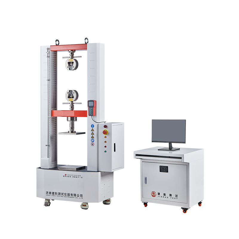
WDW-50 — Microcomputer controlled electronic universal testing machine. Product illustration. Confirm the exact configuration for your specimens.
Read the channels before judging the final number
Force is the direct loading measurement used to describe how strongly the machine pulls the specimen. Stress introduces specimen geometry into that measurement. Strain adds a separate length measurement and an original gauge length. A digital display can show all three at once, although their quality depends on different parts of the system. A high-resolution screen is therefore a presentation feature rather than proof of a complete measurement capability.
Ask the supplier to identify every channel used in a proposed result. If the requested property is tensile strength, inspect the maximum-force determination and original-area entry. If the requested property is modulus or proof strength, inspect the strain measurement and analysis region as well. Where elongation is measured after fracture, the procedure and report should make that method clear.
The word digital can cover anything from a basic force indicator to a computer system with configurable methods and exports. Describe the required functions in the purchase specification. A buyer who needs independent data analysis should request raw channel exports. A production team that uses approved reports should also demonstrate method selection and protection against unintended changes. Both applications benefit from a clear explanation of what the electronics measure and what the software calculates.
An illustrative application review
For an illustrative arithmetic check, imagine a specimen with an original area of 25 square millimetres reaching a maximum force of 12.5 kN. Its engineering tensile strength is 500 MPa. If the operator accidentally enters 20 square millimetres, the software calculates 625 MPa from the same measured force. The machine has not discovered a stronger material. This example shows why a purchasing demonstration should include dimension entry and calculation review rather than only a live force display.
Keep units and calculations visible
Force, stress, displacement, and strain describe different quantities. A force value in kN becomes stress only after division by a defined area, while strain relates a measured extension to an identified original gauge length. Keep those quantities separate in specimen entry, live display, data exports, and customer reports. Avoid accepting a column labelled strength when its stored numbers actually represent load.
As a simple arithmetic check, a 10 kN force acting over an original area of 20 square millimetres gives an engineering stress of 500 MPa. This is an illustrative calculation, not an expected result for any material or a product specification. Review rounding, significant figures, and unit conversion rules in the reporting workflow. A test system should allow the laboratory to explain how the reported property follows from the recorded measurement and specimen geometry.
Separate specimen strain from crosshead travel
Crosshead travel includes more than the extension of the measured specimen length. Grip seating, frame deformation, fixture compliance, and occasional slippage also contribute to the movement recorded by the machine. Consequently, a smooth travel curve cannot by itself establish an accurate elastic modulus or proof strength. Identify which reported properties require an extensometer and specify its gauge length, measuring range, resolution, and applicable verification.
For specimens that extend substantially, consider how the extensometer behaves after yielding and near fracture. Some devices must be removed before break, while others can follow larger deformation. Contact and non-contact solutions have different mounting and surface requirements. Demonstrate the actual measurement sequence with a representative specimen. Record any change from extensometer feedback to another measurement channel in the method and report so that later readers can interpret the resulting curve correctly.
Size the force measurement system for the actual specimens
Start with the largest credible breaking load and the smallest load that must be measured reliably. For a tensile specimen, an initial engineering estimate is expected tensile stress multiplied by original cross-sectional area. If stress is expressed in MPa and area in square millimetres, the result is newtons. This estimate helps select a configuration, but it does not replace representative sample testing. Allow for material variability and the approved operating limits of the frame, grips, fixtures, and sensor.
A high frame capacity does not establish measurement quality at every lower force. Ask for the verified working interval of each force transducer in the direction being used. A laboratory testing both strong steel and light plastic specimens may need different load cells or separate equipment. Compare uncertainty, usable measuring range, overload protection, and installation effort instead of choosing solely from the largest number on the quotation.
Evaluate low-force capability separately
A low-force specimen can expose limitations that remain invisible during a high-load demonstration. Consider the relevant force-transducer range, resolution, background signal, fixture weight, cable movement, and the force introduced while loading the specimen. The displayed number of digits does not establish uncertainty or suitability for the smallest value used in a calculation.
Ask to observe a representative light specimen with the actual grips installed, including zeroing, initial engagement, and the first part of the curve. Specify the lowest required force and the property calculated from that region. If a different sensor or fixture is proposed, confirm how it is installed and verified. A laboratory mixing light films, wire, and much stronger materials should plan the changeover carefully so that the high-capacity configuration is not used outside its justified measuring interval.
Review modulus and proof-strength calculations separately
Calculations based on a small-strain region require close attention to strain measurement, specimen seating, force measurement, and the selected fitting interval. A result can look plausible while being affected by an inappropriate zero, grip seating, or use of crosshead travel in place of specimen extension. State the calculation required by the chosen method and identify the channels that support it.
During method validation, review the beginning of the curve at a suitable scale and compare the calculated result with the recorded inputs. Define any permitted initial-region treatment and avoid choosing a fitting interval solely to obtain an expected value. For proof strength, document the offset and related settings. Preserve the calculation configuration with the test. This allows another qualified reviewer to distinguish a genuine material response from a change introduced by the analysis settings.
Keep the curve and its calculation history
A final maximum-load number is useful for screening, but it does not preserve enough information to investigate every later question. Retain the force, displacement, and strain channels relevant to the method, together with sampling settings, specimen dimensions, gauge length, and the calculation configuration. Link the data to the specimen identifier and the exact test method version.
Ask how the software handles zeroing, filtering, interpolation, excluded regions, and recalculation after a test. The objective is an understandable record rather than the largest possible file. Separate original measurements from edited presentations and identify any post-processing used to create a customer report. Export a sample dataset during acceptance and reopen it on the intended office system. This simple exercise often reveals missing units, ambiguous column names, or software dependencies before production testing begins.
Investigate variation without hiding the individual results
Repeated specimens help assess a testing process, but their differences can come from material variation, preparation, dimensions, alignment, gripping, conditioning, control, or measurement. Keep individual results and curves visible before calculating a batch summary. A narrow spread from one homogeneous material does not demonstrate the same performance across every application.
When an unexpected value appears, follow a documented investigation sequence. Check the sample record, measured dimensions, gripping marks, fracture location, method settings, and relevant equipment checks. If a repeat is justified, retain the original test and the reason for repeating it. Avoid discarding an inconvenient value simply because it differs from the batch average. Comparing carefully controlled groups can reveal which factor is responsible and whether corrective action belongs in specimen preparation, operator training, the fixture arrangement, or equipment servicing.
Make the report understandable outside the laboratory
A useful report identifies the specimen and method, states the measured properties with units, and explains relevant test conditions. Include the equipment identifier, force range where relevant, deformation measurement, specimen dimensions, rate settings, and any deviations that affect interpretation. A customer receiving the document should be able to understand the basis of the result without contacting the original operator for basic information.
Separate measured values, calculated properties, and acceptance decisions. An acceptance decision needs a documented product requirement and an agreed rule for applying it. Preserve supporting raw data and identify the report version if corrections are issued. For overseas customers, check decimal conventions, unit conversions, language, and the relationship between the report identifier and shipment records. Clear reporting is particularly valuable when a material supplier, independent laboratory, and end user need to compare results from different systems.
Frequently asked questions
Are more displayed digits evidence of better tensile accuracy?
Displayed digits indicate resolution of presentation. Measurement capability also depends on calibration, verified range, uncertainty, noise, specimen geometry, and the deformation channel used for the reported property.
What should I send with a configuration inquiry?
Send specimen drawings or photographs, material and dimension ranges, expected forces, required properties, test methods, workload, and installation conditions. Ask the supplier to identify the proposed sensors, grips, software functions, verification, and acceptance procedure. A representative sample demonstration can help resolve details that a model name alone cannot establish.
Discuss the application with Jinan Jianke
Jinan Jianke supplies material testing equipment for laboratory and production applications. Use the WDW-50 product page as a starting point for an application discussion. Send your specimen information and required method through our contact page, and request a configuration-specific proposal, documentation, and representative test evidence.
Standards references
Identify the method applicable to your material and contract, and consult its full requirements. Relevant official catalogue entries include ISO 6892-1, ASTM E8/E8M. Listing a standard does not establish conformity of a particular machine configuration or completed test.
Talk to an application specialist
Request a Quote
Share your testing requirements. We will reply with a suitable configuration and quotation within one business day.
Technical selectionWorldwide deliveryAfter-sales support